Adding Fiducial Markers and Groups
How to add fiducial markers and groups to an organ scaffold
Step 1: Create and execute a workflow
For this task, we will be demonstrating how to add user-defined fiducial markers and annotation groups to an organ scaffold. This step is usually performed to improve alignment and fitting of the scaffold to segmentation data.
To start we Create a Skeleton Dataset Structure.
Launch MAP Client Mapping Tools, found in the Start Menu under MAP-Client-mapping-tools vX.Y.Z (The X, Y, and Z will be actual numbers depending on the current stable release).
You can create a new workflow anywhere but here we will create one on the Desktop.
Using Windows explorer, or similar, create a new directory on the Desktop and name it Add Fiducials.
From the File menu in MAP Client Mapping Tools select the New workflow (CTRL-SHIFT-N) to start a new workflow.
Navigate to the Desktop and select the Add Fiducials directory created earlier.
In this example, we will create a simple workflow to demonstrate the steps of adding fiducial markers and groups. The techniques described here can be adapted for any mapping workflow and integrated in the scaffold creation step.
Add Scaffold Creator and File Location Sink to the workspace and link Scaffold Creator to File Location Sink. Click on the green wheel icon on File Location Sink and change the identifier field to output and select the output directory.
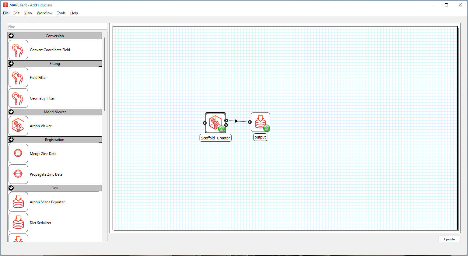
Figure 1. Workflow showing connections for scaffold creation.
After setting up the workflow as shown in Figure 1, save the workflow (CTRL-S) and execute the workflow (CTRL-X) by pressing the Execute button in the lower right corner of the application main window.
Step 2: Select a scaffold
At the Scaffold Creator interface, select 3D Box 1 under the Scaffold type and set the Number of elements 1, Number of elements 2, and Number of elements 3 to 2.
Check the box next to Marker points as shown in Figure 2 to enable display of marker points after they are created.
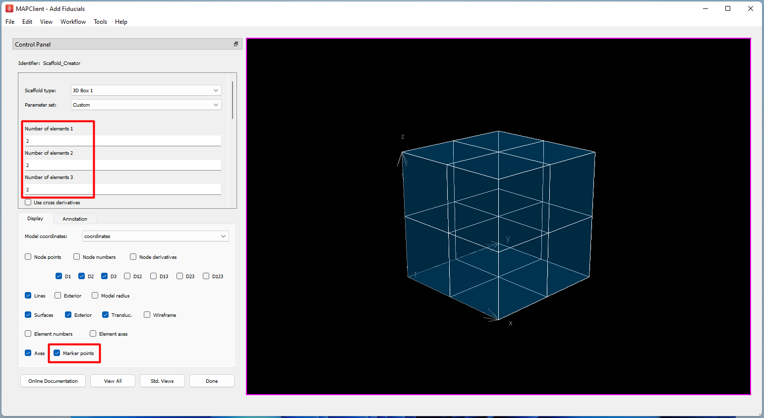
Figure 2. Scaffold Creator configured for a 3D box scaffold with 8 elements, with marker points turned on to display markers.
Step 3: Add a user-defined fiducial marker
Go to the Annotation tab. Click on the New marker button and the Group field will automatically be populated as group1. A marker point named group1 is now created and displayed at the origin of the axis.
This new marker can be customized by renaming group1 to marker1 under the Group field. If you would like to add an ontology identifier for the marker, you can enter the identifier under the ONT :ID field.
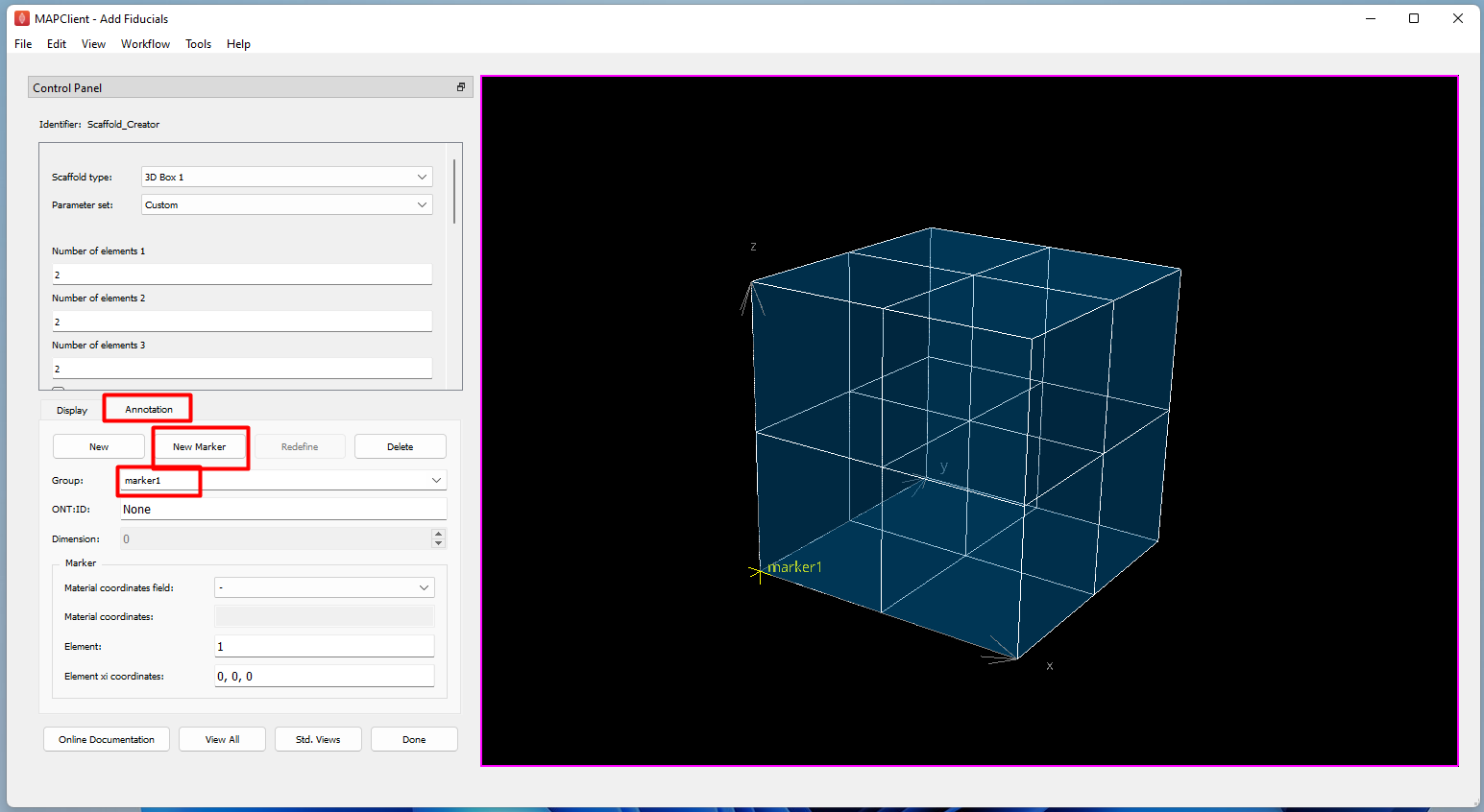
Figure 3. Addition of a new user-defined marker.
The marker location can be adjusted via two methods. If - is set for the Material coordinates field, the marker location can be set using the element number and element xi under the Element field and Element xi coordinates, respectively as shown in Figure 4.
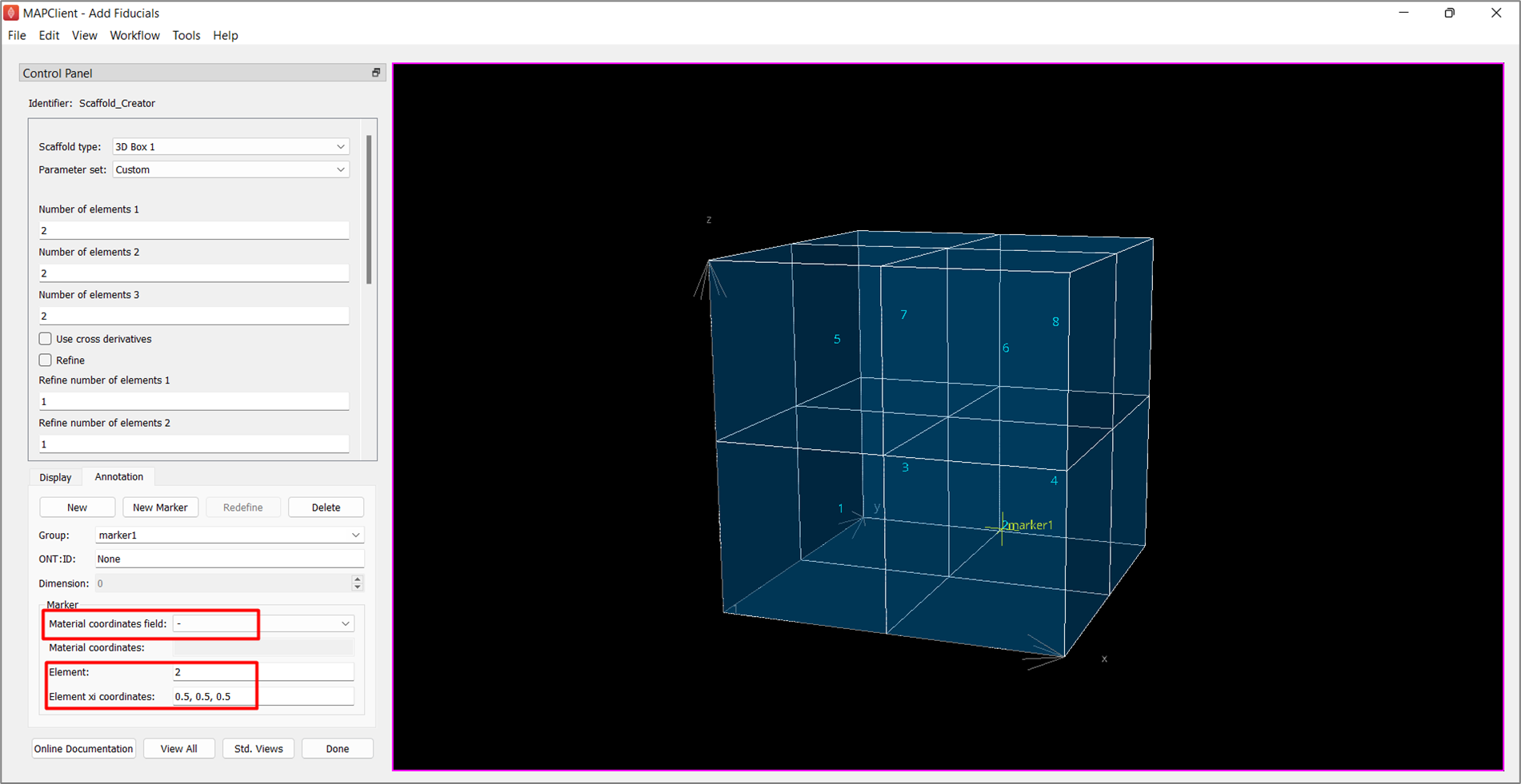
Figure 4. Setting marker location using element and element xi.
Next, add a new marker and rename it as marker2. We will use marker2 to demonstrate an alternate way to adjust the location of the marker. As shown in Figure 5, select coordinates under the Material coordinates field. Now, the marker location can be set using its coordinate values under the Material coordinates field. As this 3D box is of unit scale, setting 0.5, 0.5, 0.5 moves marker2 to the middle of the 3D box scaffold.
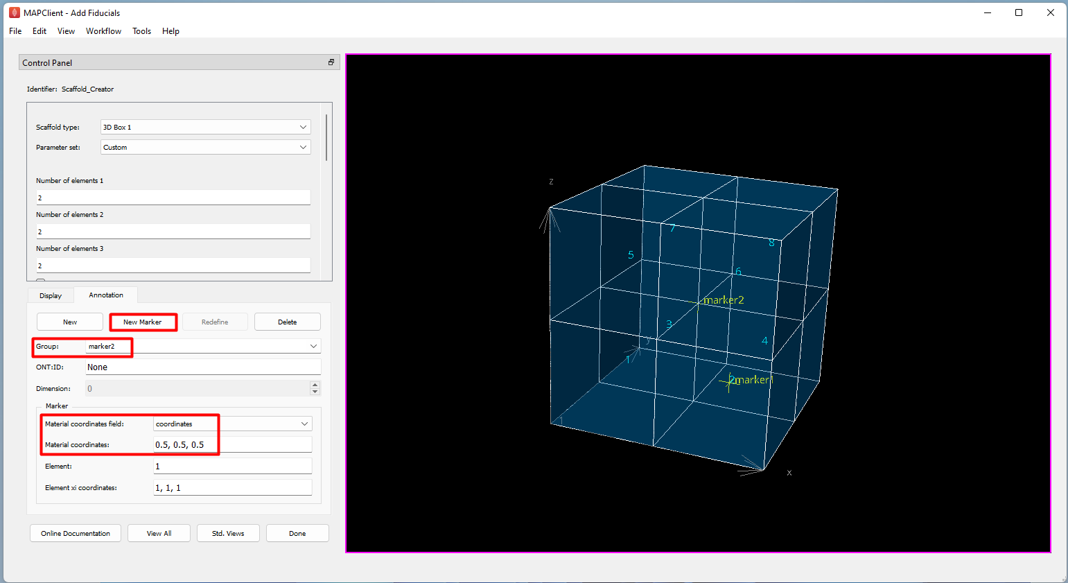
Figure 5. Setting marker location using coordinate values.
Step 4: Add a user-defined annotation group
Apart from fiducial markers, we can also create higher dimensional annotation groups for 1D lines, 2D surfaces and 3D volumes. First, make sure that no group is selected under the Group field. We then select the graphics for objects of the required group on the graphic window. Press the S key and use the left mouse click to select objects for the group you wish to create. When doing selection, make sure that the first click is in the graphic display window to give it focus, otherwise the character S could be entered as a parameter or part of the group name. To select multiple different objects (note that objects in a group must be of the same dimension), hold on to Shift+S while selecting with the left mouse. Box selection is also available by dragging the mouse, provided the initial click is away from any objects. Selecting a blank area of the screen clears the selection.
Here, we have selected a 2D surface (highlighted in red in Figure 6). Go to the Annotation tab, click on the New button and a new group called group1 will be created automatically. Next, rename group1 to surface1 under the Group field. Note that the Dimension field will automatically pick up the highest dimension of the selected objects (in this case, 2 as we have selected a surface). A group will be created for its highest dimension, plus their lower dimensional components.
We can check if the group is created correctly by toggling the drop down list under Group to another group (for example, marker2) and selecting surface1 again from the list to make sure that the correct elements for the group surface1 are highlighted in red on the display panel.
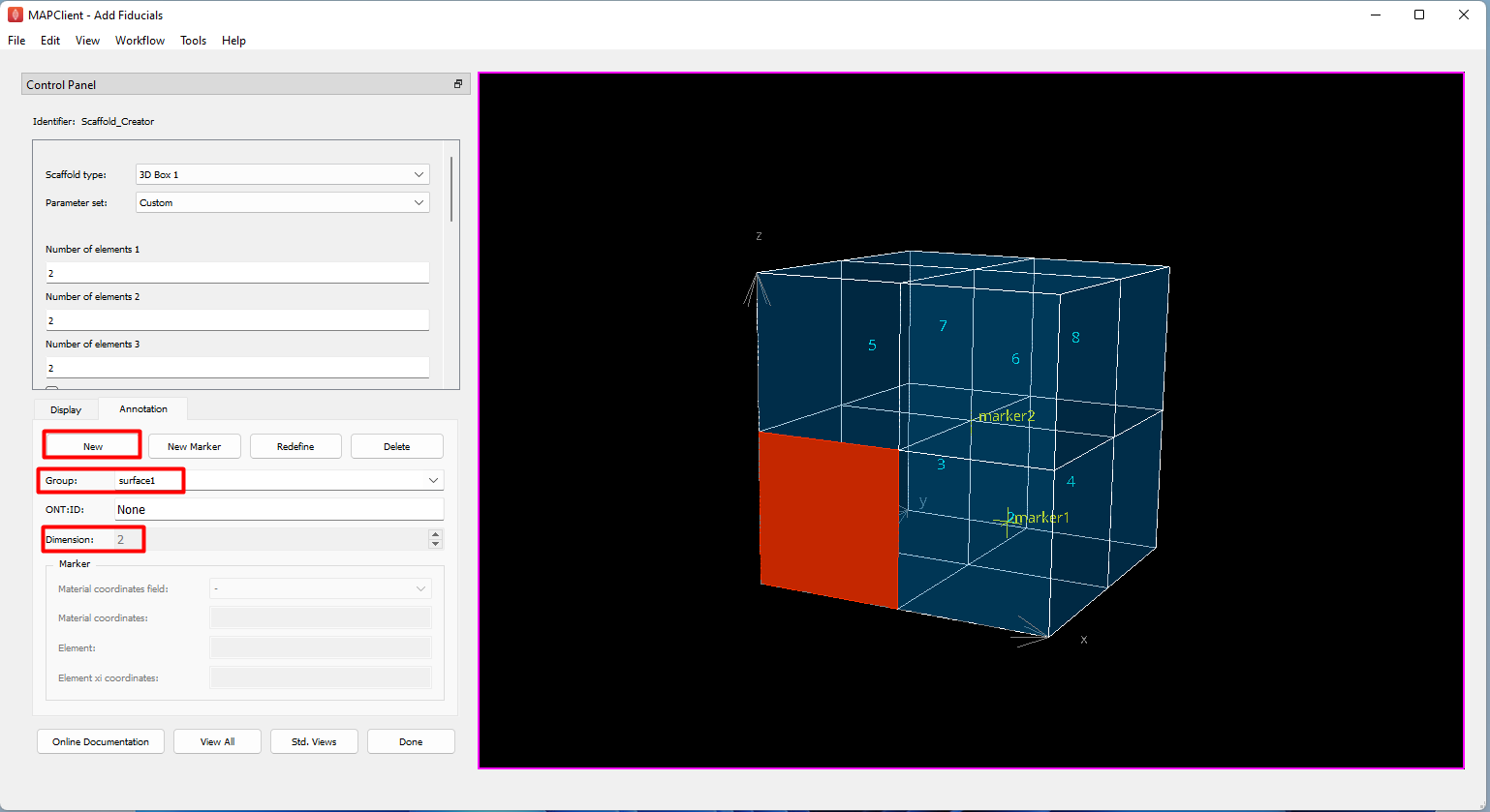
Figure 6. Adding a new user-defined annotation group.
Once an annotation group is created, it can also be redefined by reselecting the elements for the group using the S or Shift+S key, followed by choosing the specific annotation group from the drop down list under Group, selecting the Redefine button and confirming your selection (Figure 7).
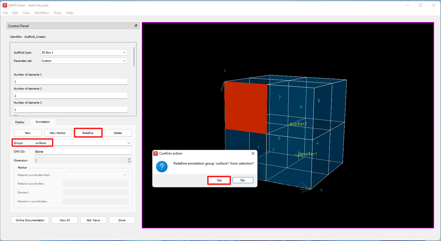
Figure 7. Redefining selection for a user-defined annotation group.
If you wish to delete a user-defined marker or annotation group, select the respective group from Group and click on the Delete button (Figure 8). Note that the ability to edit and destroy markers and annotation groups is only limited to user-defined annotations. Markers and annotation groups that are already built-in the scaffold cannot be modified or deleted.
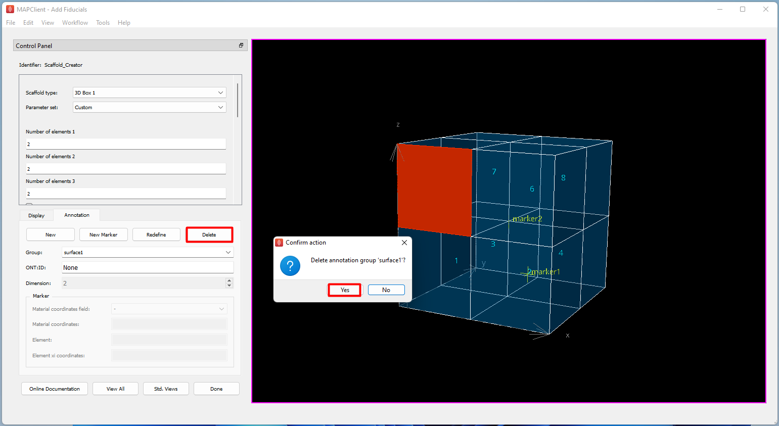
Figure 8. Deleting a user-defined annotation group.
After addition of user-defined fiducial markers and annotation groups, click Done or Next (if integrated in an image data mapping workflow) to complete the process. Information of the newly created markers and annotation groups will then be propagated to subsequent steps in the mapping process and exported together with scaffold information in the file generated by the workflow.
Return to the main MAP-Core Scaffold Mapping Tools page.
Updated 11 months ago