Introduction To CAD Modeling On o²S²PARC
In this tutorial you will learn how to view, edit and publish new versions of CAD models on the o²S²PARC Platform. We will first learn the basics and then explore a more advanced use-case: the projection of an electrode onto a 3D nerve model.
Prerequisites
- An active o²S²PARC account: if you don't have an account on o²S²PARC, please go to https://osparc.io/ and click on "Request Account". This will allow you to take advantage of the full o²S²PARC functionality.
- CAD files and basic knowledge of 3D modeling concepts: although it is not necessary, it is still nicer to follow this tutorial if you have some CAD files that you can import and manipulate.
Getting Started
Before starting, be sure you are logged in to o²S²PARC (by visiting https://osparc.io/). If you are not logged in, you will see an error message prompting you to log in.
Once you are logged in, you can start the CAD Modeling Service (Figure 1):
- Go to https://osparc.io/ and click on the "SERVICES" tab
- Type "CAD" in the search bar
- Click on the "CAD modeling" service
- Click on "Open" in the Service Details window
In this way, you create a new o²S²PARC Study containing one Interactive Service.
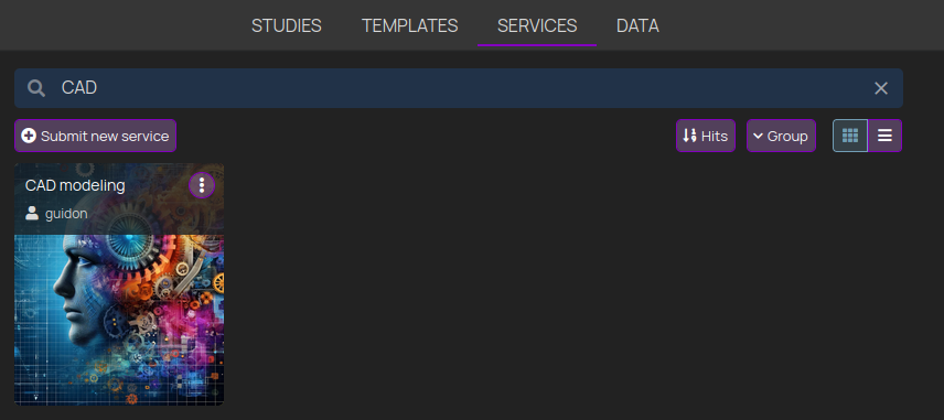
Figure 1: start the CAD modeling Service on o²S²PARC
Importing An Existing CAD File
Once the CAD modeling Service is up and running, you can import a CAD file from your computer (see Figure 2):
- Click on the burger menu in the Service UI (top right corner)
- Select "File browser..."
- Click on the button "Upload file"
- Browse your local file system to find the file and select it (double click on it)
- You will see the file in the Service "File browser "
- Close the Service "File browser" (click on the ✖️ button)
- In the Service UI, click on the "Imp/Export" button (top row in the UI), then on "Import"
- Select a file. Note: if you don't see the file, click on "All Supported Formats" and then Select "All Files (*)"
- If the operation was successful, you will see the model in the 3D view and the model elements on the left ("Modeling Tree"). If you don't see the model, click on "LOGGER" (bottom of the window) to check for errors
You are now ready to interact with the model, e.g. zooming on the 3D view, explore the model entities in the modeling tree, creating meshes of the entities, etc...
Figure 2: import a local CAD file in the CAD modeling Service
Modifying A Geometry
Depending on the properties of the CAD file, the geometry can be constituted by sub-elements. The sub-elements can be expanded in the modeling tree and depending on their type, you can perform some operations on them.
When you click on an element in the modeling tree, it will be highlighted and also selected in the 3D view (Figure 3).
In the example below (Figure 3), we see that the "Implant Model" has five different elements, each one constituted by an elementary 2D geometry of the type "Rectangle".
To modify an elementary 2D geometry:
- Click on the element in the modeling tree
- A corresponding property window will appear below
- Edit any of the properties by clicking on it (e.g. "SizeX")
- Type a new value in the field
- On your keyboard, press "Enter" to confirm (or click anywhere in the window)
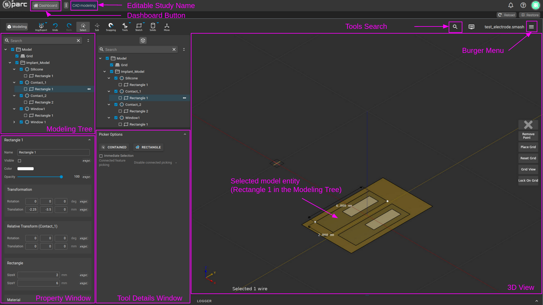
Figure 3: main elements and operations in the modeling view
Saving The Study
If you want to keep your changes, you first need to save the model geometry and then the o²S²PARC Study. All the files that are in the workspace folder will be uploaded to the o²S²PARC cloud storage (and downloaded when you open the Study again).
We also recommend changing the name of your Study, so it will be easier to find it later. To rename it, click on the editable study name field on the top of the window (Figure 3). The default name "CAD modeling" comes from the name of the Service that you used to create the Study.
To save your changes:
- Click on the burger button (Figure 3)
- Click on Save As...
- Enter a file name (the
.smashfile extension stores all the information regarding your model) - Click OK, this will save the model geometry
- In the upper part of the window, click the "Dashboard" button and confirm
- The o²S²PARC Study will be saved and you will be back to the Dashboard
Once the saving operation has completed, you will be able to access your Study again or share it with your collaborators.
Advanced use-case: The Surface Projection Tool
The CAD Modeling Service offers advanced functionality for realistic modeling of nerves and neural interfaces, among others. In this section, we will use existing models of a nerve and an electrode and we will project the electrode around the nerve (a cuff electrode). You will also learn general concepts about tools and how to use them.
With the following steps, you can search for the desired tool using the search bar, find out about its requirements and apply them (Figure 4).
- On the top part of the window, click on the search tool ("magnifying lens" icon)
- Type the name of the tool (e.g. "projection")
- Click on the search result on the left to display the tool documentation
- You will notice that the "Surface Projection" tool is grayed out, since its requirements are not met
To use the Surface Projection tool, you need a surface mesh of the entities (the electrode and nerve surfaces in this case). In the following steps, we will create a mesh corresponding to the electrode (Figure 4):
- Expand the "Implant_model" in the modeling tree to visualize all the entities
- Click on each of the entities while pressing
Ctrlon your keyboard (multi-selection) - In the top menu, select "Mesh Tools" and then "Edit Facets"
- In the bottom options window ("Faceting Settings"), click on "New"
- Edit the "Maximum Edge Length" to specify the granularity of the mesh and press
Enteror click anywhere to confirm - Click again on "Mesh Tools" and then on "To Mesh"
- In the Modeling Tree on the left, you will see that the "Implant_model" entities have a different icon, meaning that they have been meshed
Figure 4: Creating a surface mesh of the electrode geometry
In a similar fashion, the surface mesh of the nerve can be created. The requirements to use the "Surface Projection" tool are now met and we can proceed with projecting the electrode onto the nerve (Figure 5):
- In the Modeling Tree on the left, select the Electrode Surface (the meshed entity you want to project)
- While pressing
Ctrlon your keyboard, select the Nerve Surface (the target meshed entity) - You have in this way selected the two required elements to use the "Surface Projection" tool
- If you now search for the "Surface Projection" tool as above (Figure 4), it will now be active
- Select the tool and exit the search window (press "Esc" on your keyboard)
- In the 3D window, on the bottom, you will find instructions on how to use the tool
- Optionally, you can rotate the electrode by hovering and clicking on the circle. A preview of the final result will be shown
- Click on the button "Project" to apply the transformation and wait
Figure 5: find and use the Surface Projection tool to project a cuff electrode onto a nerve model
Once the task has completed, a new element will appear in the Modeling Tree and in the 3D view corresponding to the projected electrode (Figure 6).
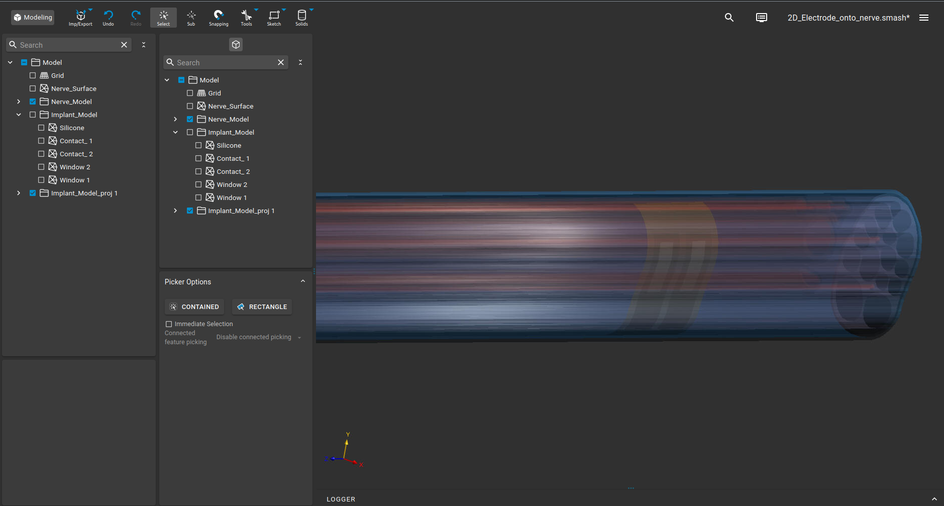
Figure 6: electrode projected onto the 3D nerve model
More information
If you would like to explore more functionality for CAD modeling and advanced electromagnetic simulations, please take a look at the full cloud software release.
Updated 11 months ago